
CQB Helmet Build Guide
- josephaguilarsanch

- Jan 12, 2024
- 7 min read
Updated: Jan 31, 2024
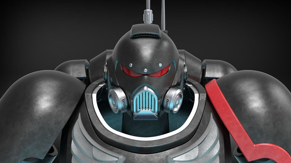
A highly customizable helmet platform for Close Quarters specialists

Full description and file set available on the main product page.
The CQB helmet comes with a suite of 8 attachments, full ventilation and audio integration, multiple bucket options, and my unique multi-part design that allows for a quick and easy assembly process
This Build Guide will list the following:
Require materials to complete the project
Assembly videos to walk you through the assembly process
Recommendations for Print Settings/Orientations for certain pieces
Any additional questions you have concerning the building of this model can be sent directly to me via the contact page on my website
Build Requirements
10 10x3mm Disk Magnets (optional)
Visor Requirements (If Vacuum Forming)
Electronics
40mm Blower Fan (For the Overhead Vent)
40mm Hobby Fans (For the Side Vents)
2x 36 mm Speakers (Hobby speakers that can be powered/connected to the Bluetooth Reciever via a 3.5 mm jack)
Bluetooth Reciever w/ headphone jack (Allows helmet to connect to your phone/computer)
*All hardware will still fit in the helmet down to 90% scale*
Assembly Instructions:
This tutorial is broken into 3 separate parts
Helmet Assembly
- This will showcase how to assemble the base helmet and attach all types of attachments
Electronics Assembly
- This will showcase how to integrate all the optional electronics
Visor Fabrication
- This will feature a full write up for vacuum forming and tinting your own visor
Helmet Assembly
The video below contains written text to illustrate how to put together the base helmet bucket.
Insert Face Plate into the Neck Brace through the top (if print the default single piece Neck Brace, you may have to slightly flex optn the Neck Brace to get the Face Plate to fit.). This may not be necessary if you print the multi-part version of the Neck Brace for Smaller Printers. In this case, you can assemble the Neck Brace around the Face Plate.
Insert the Cheek Ports (Small and Large) as well as the Cheek Tubes. The hole behind the Cheek Tubes is so that you can poke them out if you need to remove them.
Assemble the Heat Sink and insert into the helmet. There are small insert channels to fit the ends of the heat sink but the Heat sink will need to be kept in place by some glue or adhesive.
The Top Bucket comes in two halves for ease of printing and is held together by the 4 alignment pegs. These two halves can be glue together at any point or not at all. The seam that connects them lies along the same seam as the external plates so it should noticeable.
The Top Bucket and the Neck Brace/Face Plate are held together via 3 printable Screws. The screws can be turned with any needle nose pliers or two alan wrenches. If you dont want to use the screws, there are pegs of equal diameter that can be used to hold the helmet together in the same holes
You can also insert the attachment ports. There is a closed version and an open version that fits the attachment rod which is what all the side attachments mount upon.
Place the External Plates and hold them in place with the External Ports
There are two versions of the External Ports. A closed version and an Open Ports version for increased ventilation if desired.
You are complete with the base helmet! Time to move on to the attachments!
Electronics Assembly
Below I will highlight all the compartments and accomodations for the various peripheral devices that can be added to the helmet. As a reminder, the helmet can be scaled all the way down to 90% and still fit all the peripherals mentioned in the parts list. All parts can be fastened with hot glue or doublesided adhesive tapes, velcro, etc.
Starting off, there is a large compartment in the back that can be used for a AA battery bank or general storage

Leading from that battery bank compartment are channels for wires to feed to the overhead blower fan, side speakers, or side fans.

The speaker fit inside a cavity next to the large storage/battery bank compartment. If you only want to use speakers, the speakers themselves dont require external power. You can lead them straight to a bluetooth reciever which can be stored in the large rear compartment, or two a 3.5 mm jack.

These side compartments houses the side fans and blows over the external "heat sinks".


Lastly, There is an overhead fan compartment that vents air in or out from the top of the helmet. This has wire channels leading to the rear battery bank and will prevent your visor from fogging.


Attachments Tutorial
The tutorial below shows how to attach all the various attachments to the CQB helmet, including the CQB unique attachments
Additional note for the flashlight ring: it can replace any external port, but you will need to mirror it to switch sides. It is not angled properly to be used in the central port. There are two fastening screws, the longer one is for flashlights that are much thinner than the flashlight mount.
Vacuum Formed Visor
The files include a 3D Printable Buck to allow those with experience in vacuum forming to produce 100% accurate visors. I will create a separate build guide in the near-future for those not experienced in vacuum forming.
Whether you choose to print the visor or vacuum forming, the visor is held in place via several tabs built into the helmet

General Printing Tips
I have a few printing tips to give on certain pieces to ensure that you get the best print quality. These are just recommendation and are by no means the only way that these parts can be printed.
First you should decided whether you want the standard slip-on version or the magnetically sealed version. As with my other helmets I included a magnetically removable neck peice for additional clearance, but due to the CQB's geometry, it does not add more than a few mm's of clearance. You can absolutely print the standard version with no magnets and have a helmet that does not make you look like a bobble head.
That being said, the first pieces to print of this helmet should be the sizing ring. It can be printed flat and only takes 1-2 hours. In the long run this will likely save you hours if not days of printing when you can be sure that you will print the helmet at the correct scale the first time around. Keep scaling the rings up or down till you find your ideal fit and then scale the rest of the helmet to that scale. While there is a demo model that can be used for things like armor smith, this will ensure that the opening of the helmet can fit over your head. The "neck" of the sizing ring assembly is equal in shape and size to the opening of the helmet.
The pieces are not pre-oriented so you will have to adjust them to ensure they are in an orientation more optimally for printing (flat surfaces touching the build plate). Additionally, for pieces that have no ideal flat surface, I highly recommend using the Cylindric Custom Support downloadable plug-in for the Ultimaker Cura Slicer. It allows you to place custom supports on parts to ensure that you can get much safer and reliable prints on parts with odd geometries. Some of the examples below will show these custom supports, you will need to add them, or something similar to your own prints.
Optimal Print Orientation
Load Bearing Pegs/Screws/Rods
All Pegs should be printed as shown, this will ensure the layers aligned with their longitudinal axis and prevent Pegs shearing apart in the helmet.

The following pieces would benefit form this orientation
Attachment Rod
Alignment Peg x4
Body Peg x6
Body Screw x6 (Additional tolerances were included to make up for this orientation introducing support faces to the screw faces)
Heat Sink Core x2
Neck Brace Peg x2
General Piece Orientation
The Front Bucket Panel has a flat front face that can certainly be used to print the piece but will introduce some overhangs near the top that may or may not require supports depending on your overhang and bridging abilities/settings. An alternate way of printing this is to angle it such that those overhangs are no longer and issue and stabilize the whole print with custom supports, this is the orientation that I used.
*Additional Tip: Any arches or circular holes (such as the screw channels) are self supporting and you can use support blockers to remove unnecessary supports from these areas.*


The Rear Bucket Panel also has a flat face that is ideal for printing. This will still have lots of supports for the internal battery cavity.

Either version of the Face Plate should be laid flat on the build plate and printed using custom supports.

Any version of the Neck Brace should be printed similar to the Face Plate, flat with custom supports

External plates can be printed on their "rear facing" face, shown below. This ensures the hole for the external port does not require any supports, and all required supports are just on the rear face.

Various pieces have flat faces built in for ease of printing, those are listed below

Cheek Ports Small and Large
Attachment Ports Open and Closed
External Ports Open and Closed
Heat Sink (supports still advised to widen the base)
Cheek tube (supports still advised to widen the base)
Below you can see the my printed prototype of proof of the efficacy of the tips above. This print was a blast and I really enjoy just being able to slip the helmet on without worrying about losing the magnetic piece in the back. Pic is in the new painting booth I built, so I'm looking forward to finally going back and painting all the past projects I have had piling up.