
Firefall Build Guide
- josephaguilarsanch

- Jul 3, 2023
- 5 min read
Updated: Oct 12, 2023

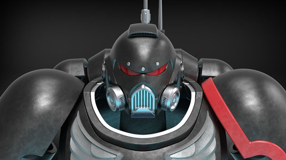
The Firefall helmet platform is the most customizable MJOLNIR helmet platform ever design with thousands of possible combinations of helmet configurations. 10+ attachments, as well as two different bucket configurations, all paired with a glueless design, makes for a helmet platform that can be made completely your own
For a full write up of all the features you can find them listed on the main product page.
This Build Guide will list the following:
Require materials to complete the project
Assembly videos to walk you through the assembly process
Recommendations for Print Settings/Orientations for certain pieces
Any additional questions you have concerning the building of this helmet can be sent directly to me via the contact page on my website
Build Requirements
Ten 10x3mm Disk Magnets (both magnets will fit the helmet scaled all the way down to 85%)
Visor Requirements
Non-Required Hardware
M2 Bolts (To secure the side attachments and flashlight mounting ring)
9V battery holder (The 9V or the AA batteries are to power the fans)
Up to a 40mm circular speaker (Hobby speakers that can be powered/connected to the Bluetooth Reciever via a 3.5 mm jack)
Bluetooth Reciever w/ headphone jack (Allows helmet to connect to your phone/computer)
Assembly Instructions:
This tutorial is broken into 3 separate parts
Bucket Assembly
- This will showcase how to assemble the base helmet and attach all types of attachments
Electronics Assembly
- This will showcase how to integrate all the optional electronics
Visor Fabrication
- This will have two different tutorials: a simple, template based visor and a full write up for vacuum forming and tinting your own visor
Bucket Assembly
For the Firefall helmet platform, I created this video w/ written text to illustrate how to put together the base helmet bucket.
Electronics Assembly
This video w/ written text illustrates how to integrate the electronics into the base helmet
Visor Fabrication
The famous ODST style visor has always been a tough one for those new to cosplay to tackle, so I added a number of different fabrication options.
Basic Template Tutorial
Vacuum forming can be a very daunting task for those without the experience and equipment, so I put together this simple visor system that will allow you to cut out to separate visor panels using 3d printed templates. These panels can be folded into the helmet itself to get a close approximation to the actual in-game visor. This can be used for really any ODST style helmet
Vacuum Formed Visor
The files include a 3D Printable Buck to allow those with experience in vacuum forming to produce 100% accurate visors. I will create a separate build guide in the near-future for that process but know that you will be able to follow along in-order to create visors such as this!

General Printing Tips
I have a few printing tips to give on certain pieces to ensure that you get the best print quality. These are just recommendation and are by no means the only way that these parts can be printed.
The very first pieces to print of this helmet should absolutely be the sizing rings. They can be printed flat and only take 2-3 hours for the set. In the long run this will likely save you hours if not days of printing when you can be sure that you will print the helmet at the correct scale the first time around. Keep scaling the rings up or down till you find your ideal fit and then scale the rest of the helmet to that scale. While there is a demo model that can be used for things like armor smith, this will also ensure that the throat of the helmet can fit over your head. The "neck" of the sizing ring assembly is equal in shape and size to the throat of the helmet.
The pieces are not pre-oriented so you will have to adjust them to ensure they are in an orientation more optimally for printing (flat surfaces touching the build plate). Additionally, for pieces that have no ideal flat surface, I highly recommend using the Cylindric Custom Support downloadable plug-in for the Ultimaker Cura Slicer. It allows you to place custom supports on parts to ensure that you can get much safer and reliable prints on parts with odd geometries. Some of the examples below will show these custom supports, you will need to add them, or something similar to your own prints.
The electronics suite has a nice flat surface in the rear that can be aligned to the build plate. The external faces with supports will likely need to be sanded down smooth to ensure a nice fit with the other main bucket pieces.

Simlarly, the vent covers also have a rear flat surface that is good for printing

For the thin vent rail, I recommend selecting the bottom of the hinge arms to align with the build plate.


This will ensure that the layer lines run along those arms and reduce risk of snapping. Keep this principle in mind for other pieces such as the Bucket Alignment Pegs, chassis alignment rods, or Master Pegs. I would warn against this for the Master Screw however as this could effect the screw tolerances.
The Bucket Rear piece has a nice flat surface where the bucket alignment pegs insert.

While there is a similar flat surface on the bucket front piece, I recommend printing it in the orientation that it comes in. It will required custom supports on the little brim piece that actually touches the build place and some large ones right on the corners of the overhang. You can also remove the need for supports on the little overhands where the magnets insert. I have printed 3 buckets in this orientation and have not run into any issues.

The central air intake does not have an ideal orientation, so for sake of print speed, I set it on its side. It is likely you will have to sand the sides to ensure it can smoothly slide into the main bucket.

Both types of attachment ports can lie flat.

The speaker cap's internal face is completely flat

The Chin UA attachment has a flag bottom face

The UA Visor Brim attachment does not have any ideal print orientation but I like to slightly angle it upwards until there is just a slight overhang left on the top ledge there. I still want the entire bottom surface to get standard supports so I dont angle that too high. For reference I use 70 degree support angle. Additionally as this will cause it to start printing on a corner, I like to put a small cylindrical support right on those corners

For the Neck base, I like to set it on its back to make sure there are no supports on the internal wire channels. Additionally I like to prevent any supports from printing inside the chassis alignment rod channels. Lastly I put some cylindrical supports on the overhang where the latch accent goes to ensure it has a stable platform to start printing


Lastly, the CBRN attachment has a flat rear face, and the Outer Vent has a flat surface on which it can be printed.