
Grenadier Build Guide
- josephaguilarsanch

- May 25, 2022
- 11 min read
Updated: Oct 12, 2023

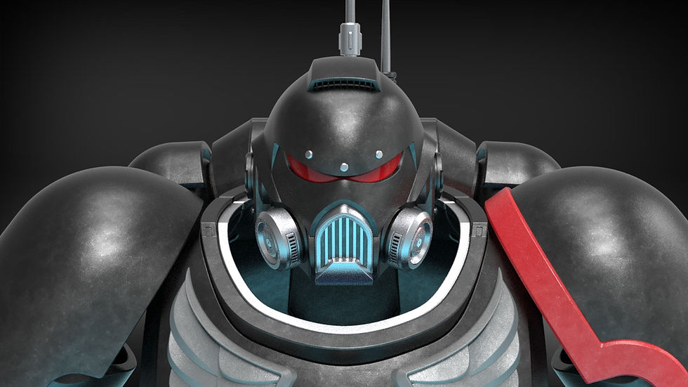
Jorge's iconic helmet was the first helmet where I experimented with my unique style of breaking up helmets like a 3D puzzle, broken up by natural seams and color patterns. Over time, I revisited the project to update it for features like additional attachments, fan/light support, vacuum form visor, support, multiple customization options, and to refine some of the designs of the interlocking pieces For a full write up of the many features and customization options you can find them listed on the Grenadier Product Page
This Build Guide will list the following:
Require materials to complete the project
Assembly videos to walk you through the assembly process
Recommendations for Print Settings/Orientations for certain pieces
Tips for sanding/painting
Some of the formatting of this Build Guide will differ from newer build guides as this build guide was taken from an older post and reformatted and updated so that it could be included in the Build Guides Section
Any additional questions you have concerning the building of this helmet can be sent directly to me via the contact page on my website
Build Requirements
Visor Requirements
Vacuum Formed Visor
Resin Visor
Non-Required Hardware
Up to a 40mm circular speaker (Hobby speakers that can be powered/connected to the Bluetooth Reciever via a 3.5 mm jack)
Bluetooth Reciever w/ headphone jack (Allows helmet to connect to your phone/computer)
Assembly Instructions:
The video below shows a video of me putting together my finished Grenadier Helmet. This build was from the oldest version of the helmet. Since some of the pieces have been updated to offer additional customization options, I will write out the instructions below as well to point out any additional steps.
We will start with the Side Plates as most of the other pieces connect in some form to the Side Plates. The Vented form of the Side Plate comes with Fan Accomodations and ducting
Attach your desired Cheek Plate to the front of the Side Plate. The Cheek Plates also come with Vented/non-Vented options. The Side Bars/Side Lights have options for both Vented/Non-Vented and can be attached to the Cheek Plate.
Insert your desired Ear Piece into the Side Plates. Ear Pieces will vary depending on whether you want attachments and/or speakers.
Repeat for the opposite Side Plate
Now we will assemble the rear of the helmet, starting with the Neck Base.
Slide the Neck Support onto the Neck Base using the alignment features on the middle
Slide the Neck Top onto the Neck Support using the alignmeent features. There are different versions of the Neck Top for whether or not you want the chip insert detail present on the helmet
Next you can attach your Main Cap onto the Neck Top. There are different versions of the Main Cap for whether or not you want the chip insert detail present on the helmet. You can Attach the Temple Ornamentations to the Main Cap at any point.
Next we will switch to the front of the helmet, Starting with the Mouth Plate. You can attach the Jaw Ornaments and Chin Ornaments to the Mouth Plate at any time
You will need to connect the Face Plate Top and Face Plate Bottom to each other and Attach the Top Alignment Keys to the Face Plate Top. Once they are connected, attach to the Mouth Plate
Attach the Face/Mouth Plate to the Main Cap via the Alignment Keys in the previous step
At this point, the entire central portion of the helmet should be assembled and you can secure them all to the Side Plates. Now you can attach your chosen Visor and secure with the Visor Screws. There are different versions for whether you want the UA attachment or not and if you want the overhead fan or not.
Now you can insert your resin or vacuum formed visor.
Lastly you can attach your side attachments to the Ear Piece via the attachment rods
Visor Fabrication
Vacuum Formed Visor
The files include a 3D Printable Buck to allow those with experience in vacuum forming to produce 100% accurate visors. I will create a separate build guide in the near-future for that process

Resin Visor
Multiple Visor options.

This model includes a full kit to help you make a mold capable of casting a resin visor. A resin visor in and of itself will have some reflective properties while more importantly allow you to make the visor see-through and a color of your choice. It also allows for more complex geometries than vacuum forming and makes for a sturdier visor. I went with a simpler mold shell design without an alignment baseplate for this design. The visor and mold shell sheathe together, so just ensure that the visor plug is not touching any of the walls before pouring in the molding agent. As usual, I recommend glueing the two pieces to a flat piece of cardboard. The mold shell is designed to be able to flip over and stand flat when pouring in Resin to ensure the top does not leak or pour resin.
Visor Resin Volume: 192 mL
Visor Rubber Mold Volume: 621 mL
My Personal Experience is documented below


1: I glued the visor to an old pizza box.
2: I then placed the mold shell over top the visor plug and used spray adhesive to keep it in place. I would not recommend this because it turns out it was not a tight seal and I had some silicon leakage. I would recommend hot glueing it to ensure you have no leakable areas. I used spray adhesive because I was impatient.
3: Next I removed the visor from the mold and placed the mold back in its shell. If you cant remove the mold without destroying the shell, you can always just print another, this is why I make the shell so thin, to save on materials. For my next project I will be experimenting on two piece shells, held together with small bolts.
4: Next determine how much resin you need, I list the amount earlier in this post, however, if you decide to scale the helmet, you'll need to do a bit of math. Mix as instructed with whatever dye you want.
5: I have a small vacuum chamber, so you can see I putt out the bubbles with that
6: I pour the resin into the mold, and since I included a little extra just in case too much gets stuck to the cup/mixing stick, I pour the excess into some small gem molds I made the other day.
Below you can see that the visor initially comes out pretty cloudy. After I sanded/polished it you can see that it starts to become see-through.


For this process I usually go 600>1000>1500>2000>3000 grit sandpaper on the visor. Lastly, and most importantly I finish with a microfiber cloth and Flitz polish.

Also note, that the resin visor is somewhat malleable, so when putting it in your helmet you can squish it so that it fits through the throat if it stretch out during the polishing process. In my experience It takes a lot of force to deform it so it is still pretty sturdy and does not effect the polish.
Visor Insert Features

The inside of the helmet features Guides to hold the visor in place. While the visor can sit on these alone I would recommend a low strength glue or tape to help fasten hit while still allowing you to remove the visor.
Electronics Assembly
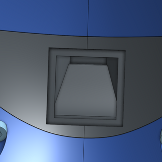
Ventilation System
The newest feature, and the one I am most excited about, is the added ventilation system. The side plates and cheek plates now feature a square slot to fit hobby duct fans. This slot is connect via duct to the front of the helmet, where there are several options for small printable vent covers. The slot is a 52 mm square, so it should be able to fit 50mmx50mmx15mm duct fans with ease.


Here are some pics of the two printable vent covers.


Additionally ventilation was added to the top of the helmet and is only usable with the UA attachment. The slot is a 42mm square and should plenty of room to attach a 40mm hobby fan.


Forward Lighting Accommodation
Directly underneath the side duct ventilation is a separate channel and casing to accommodate various lighting fixtures of your choosing


Integrated Sound System

Each ear piece comes with a circular hole to easily insert 40mm hobby speakers. The hole is 42mm wide and features a large bottom square feature to allow for wires to easily pass through.
General Printing Tips
I have a few printing tips to give on certain pieces to ensure that you get the best print quality. These are just recommendation and are by no means the only way that these parts can be printed. This helmet features many curved surfaces so many of the pieces dont have an obvious flat face to print upon, unlike my future helmets. So because of that, I added some tips below and things to consider about the orientation.

The very first pieces to print of this helmet should absolutely be the sizing rings. They can be printed flat and only take 2-3 hours for the set. In the long run this will likely save you hours if not days of printing when you can be sure that you will print the helmet at the correct scale the first time around. Keep scaling the rings up or down till you find your ideal fit and then scale the rest of the helmet to that scale. While there is a demo model that can be used for things like armor smith, this will also ensure that the throat of the helmet can fit over your head. The "neck" of the sizing ring assembly is equal in shape and size to the throat of the helmet.
The pieces are not pre-oriented so you will have to adjust them to ensure they are in an orientation more optimally for printing (flat surfaces touching the build plate). Additionally, for pieces that have no ideal flat surface, I highly recommend using the Cylindric Custom Support downloadable plug-in for the Ultimaker Cura Slicer. It allows you to place custom supports on parts to ensure that you can get much safer and reliable prints on parts with odd geometries. Some of the examples below will show these custom supports, you will need to add them, or something similar to your own prints.
**For my future helmets I mostly use locking pins/pegs. For this helmet I used these alignment pegs that come pre-attached to the print. If you want to ensure that the peg is as strong as possible you can align the print such that the layer lines go through peg and print body. If it is oriented such that the narrow connection point of the peg is its own small layer, it is much more likely to break off.**
Starting with the most intimidating piece, the main cap. I recommend printing in the following orientation, using some cylindrical supports to give added stability. This will ensure that a majority of the helmet does not require suports and the pieces that do require supports are on the top smooth surface of the helmet which will make it the easiest spot to sand away.

Next for the overhead visor/brim. The rear face has a flat face you can use to print and just in case you are worried about the overhang of stability, you can add some supports where I have below

For the Face Plate, I recommend printing both flat on the build plate. The bottom piece does not have a flat bottom so I recommend adding custom supports all along its base.

For all the Neck pieces, they do not have any flat faces so there is a few things to consider. They can be printed flat along the build plate, but wince they have slight curvature, you will have some supports that you will have to remove and you may have to sand that surface to ensure it still slides into place correctly on its neighboring piece. Other wise you can print them in an upright "U" shape to ensure that all the tolerances are as they should be. This will leave a rough surface where the supports were on the outside of the helmet, but that will be in a spot that is easily sandable. The latter is the method I used.

For the Side Plates there is a flat surface on the rear that you can align with the build plate and print mostly vertically.

For the Mouth Plate, you can print on its bottom but you may have issues with the sharp over hang where the Jaw ornaments go. If you print on its front face you will minimize supports and get rid of any issues with the edges/overhangs. You will have to sand the surface where the supports are but if will be in a spot that is easiest to sand. The latter is the orientation I used.

Sanding/Post Processing Tips


I am no master prop maker, but I could not anticipate how well this helmet came out!
The multi part design made sanding and painting each individual part much easier and allowed me to get a glossy smooth finish all the way up to each edge on the helmet. If the helmet was one solid piece, all the nooks and crannies would've been a real pain to try and smooth and would probably have lead to visible layer lines on all those inner edges.
When painting this model, I was able to get such a glossy finish by using a new technique of alternating between primer and bondo.
- First, apply a layer of sand-able filler primer to you initial 3d print.
- Next, sand away as much of that layer as you can with one quick pass of sand-paper, electric sander, dremel, etc. You should still have some spots where you still see the primer in the deeper layers, more uneven areas. I usually use 80 grit for this. This is not meant to get the object super smooth, mostly just to show you where bondo will be necessary
- Next, apply bondo to the spots where you still see the gray primer. I usually wet sand this away with 600 grit. This works well with the bondo shown below. If you get the bondo that is not premixed and comes with the hardening agent, you may need to use higher grits to get through it in a timely fashion. Again, don't spend too much time on this layer either, just make sure you sand enough away so that all the previously grey/primered areas are now red and smoother than they were before.
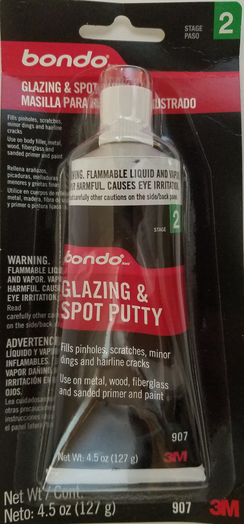
- Next add another layer of primer, wet-sand this with 600 grit till your model is now smooth. You should be able to see light reflect of the primer at this stage. I recommend 600 grit because it tends to hit the sweet spot of smoothing the paint, but also sanding the paint away quickly if its still not perfectly smooth. This will make quick work of swirl lines from the previous grits.
- At this point your piece should be mostly shiny-grey. You may see some small problem areas at this point, so repeat the previous two steps in these small spots as necessary.
- Lastly, you apply your paint! For this project I chose glossy enamel paint. The enamel paint tends to be hardier and stick to the props better. They are also more resistant to damage. Additionally if you need to sand it, it sands slower and can act the same as the primer from previous steps.
The piece that require the most repetitions of these two steps were the main helmet, especially because that raised feature on the top was not originally connected and I had to glue it in place and get rid of the seams. I have since changed the model to have these two pieces come connected. Additionally I printed the main cap upside down so the entire top of the helmet had horrible quality due to the supports and me getting them off. But as you can see in a lot of the pictures, despite this piece being the roughest by far, I was able to get it to a mirror-like finish.