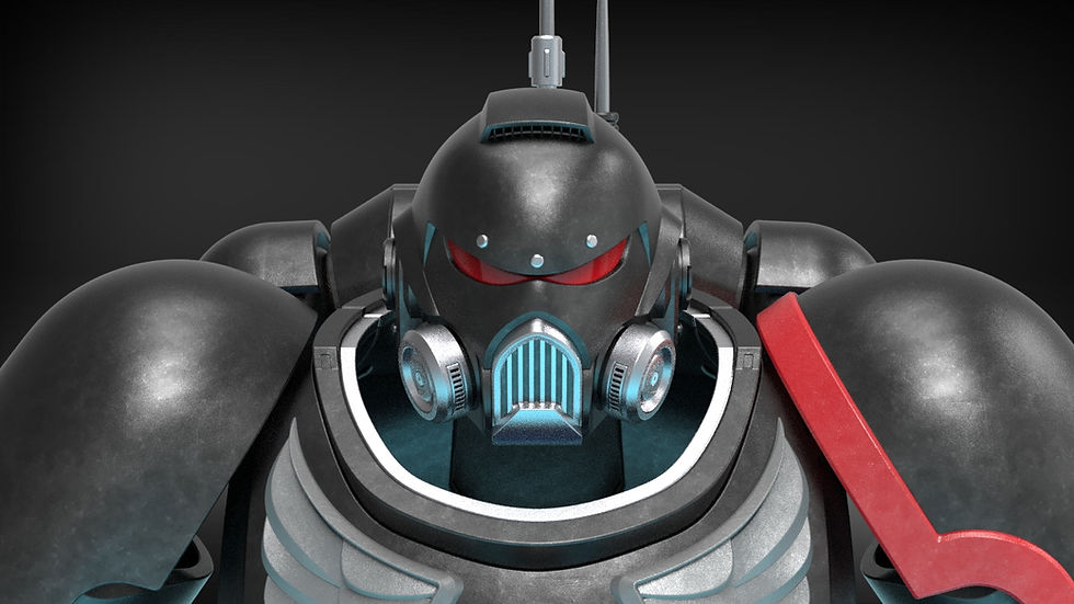

Sister of Battle Armor Guide
- josephaguilarsanch

- May 22
- 16 min read
Updated: 4 hours ago
Prove your undying loyalty to the God-Emperor and recite the imperial hymn as you print your own functional Sister of Battle Armor

Helmet is included in the full set
Generic ornamentation has been included. It is all separately printable, so you can add whatever ornaments you wish to fully customize your set as you wish. Contact me if there are specific ornaments you would like to see.
This Build Guide will list the following:
Required materials to complete the project
Written instructions for all armor pieces
Written instructions for both variants of the helmet
Recommendations for Print Settings/Orientations for certain pieces
Any additional questions you have concerning the building of this model can be sent directly to me via the contact page on my website
Build Requirements
Any 3D Printer with build volume as small as 250^3 mm.
All larger pieces come with sliced options that fit the above dimension.
This assumes printed at default scale, which is scaled to fit a 6ft battle sister
It is highly advised that you use a flexible filament such as TPU air for the shoulder tubes as they form a connection between the shoulder and the chest harness. The shoulders have strap integration loops to keep the shoulder secure to the body so the tubes can be flexible to allow for shoulder articulation without having to focus on providing rigidity/strength.
It is optional but still a good option to print things like the leg armor and breast cups out of similarly flexible/soft filaments
The amount of each filament will depend largely on the scale you print the armor as well as infill percentage. In my experience 12-15% infill with 2 shell walls is more than enough for most wearable cosplay armor. Anything above 20% will just increase the weight with diminishing returns on strength
Helmet:
(You'll need up to 12 individual magnets for the mechanical helmet assembly, up to 20 individual magnets for the simplified helmet.
Up to 8 individual magnets can be used depending on which helmet assembly you choose. (4 for mechanical assembly, 8 for the simplified assembly. Used to hold Hinge Rib that covers the Hinge Screw.)
Optional Hardware
Visor Requirements
The visor was designed to work as one flat curved piece so no vacuum forming is necessary. Printing the lens template will allow you to cut your visor to size to fit within the helmet.
Armor:
This strap size will fit all of the various strap accommodations on the shoulder plates, chest, legs, hip plates, knee pads, and sabatons. Keep in mind that if you scale the armor down, you may want to scale the straps down to 1" as well.
This is for magnetically attaching the optional breast cups to the chest armor. The breast cups can be glued on as well.
Armor Assembly

Chest Harness/Gorget:

We will start with the Chest Harness or "Gorget"
The Chest Harness is meant to act as a singular piece that slips over the head. It has two larger flat pieces where they meet the shoulders to reduce pressure on the wearer's traps and shoulders. There is also a inward curving slope on the sternum to reduce the pressure on the wearer's chest. Both these spots can be further improved by your own padding/vest.

If printing the sliced version of the Gorget, you will have to glue the four pieces together. Large overlapping alignment patterns will ensure that even the sliced version will be strong enough to support the torso of the armor.

The Chest Harness features two sets of strap loops. The strap loops above the shoulders are meant to serve as a connection point for the corresponding strap loops on the shoulder plates. This should be used to support a majority of the shoulder plates weight. Padding and additional straps can be placed under the large shoulder plates if desired to increase comfort/security of the shoulder plates about the shoulders.

The second strap loops are on the front and rear of the Chest Harness. These allow for straps that go underneath the arms and connect the rear and front of the harness. These can tighten around the users sides to or clip into a vest to assist in keeping the harness secure to the body. This can also serve to help keep the harness in place against the weight of the power pack pulling the harness backwards. If properly sized the harness should have a large surface area sitting flush against the users back that should also serve to keep the power pack and harness from tipping backwards. Keep in mind that the front strap loops also serve as the inlet ports for the ventilation system, so try not to completely block those ports. You can utilize the rear most rigging points to ensure there is still one open to supply air flow to the users chest and neck.


There are magnetic attachment points to allow for the attachment of the armored breast cups. Any combination of magnets, glue, or tape can be used in conjunction with the semi circular alignment keys to ensure the breast cups are kept in their proper place while maintaining either a permanent or semi-permanent hold.
The standard Gorget does not feature these alignment cavities. The modified variant can be found in the folder containing the various armored breast cups. Both Gorget's look the same when viewed from the outside. So if you do not yet know if you want armored breast cups or a softer brigandine that you fashion yourself, you can always utilize the Gorget variant that is compatible with the breast cups.


There are two variants of the breast cups, the standard and the completely smooth variant. The smooth variant allows for more easily incorporating your own custom emblems, but there are options such that all the included emblems work with either breast cup.


The following emblems are included in the default set
Chest Emblems:
Fleur de Lys
Skull
Sister Superior Inquisitorial w/ separate skulls
Breast Cups:
Fleur de Lys
Two Sizes of Skull, small and large
The Chest Harness also features to tubing ports in the rear and the front, these are meant to support the tubes that connect the shoulder plates to the chest and power pack. As the rear ports sit in the mounting block, there is a large internal cavity that you can mount smaller fans to. These fans can help force air from the main duct in to the chest feeding, side tubes. These openings are approximately 23mm

These tubes are hollow to allow airflow from the power pack to the chest and neck. These tubes should be printed out of something flexible or substitute out of flexible corrugated tubing to allow for the shoulders to articulate.
If substituting the tubes, the ports in the chest/shoulder feature a 34mm inner diameter when printed at default scale.

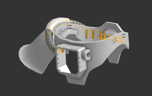


All rivets and emblems are printed separately to allow for printing in different colors, ease of sanding/painting, and your own customization preferences. I have highlighted all the standard rivet points for your own reference.

Power Pack


The power pack is comprised of two major components.
The Body is the lower part of the back pack where a majority of storage and electronics can fit. This also serves as the attachment point to the main Chest Harness via a series of pins.
The Top is a separate module that contains the "Power Generators" and can be removed from the body via a series of pins. The power generators can also be screwed off in order to access the inside of the power pack without doffing the armor.
Starting with the Body, it features several panel inserts which are hollow to allow for additional storage capacity for things like batteries. Two of the side ports serve as air inlets to allow outside air to be pulled into the power pack from the outside.

The body features the internal attachment block and this block features a number of pins that can be used to secure the power pack to the chest harness. This attachment block also serves as a large mounting face for a large central fan or fan array. The face is approximately 160x164mm when printed at default scale. The opening for airflow is approximately140x145mm.


The Topper features two variants, one for the standard battle sister and one for the sister superior. The sister superior features two insert points for the sisters superiors arch ornament.
The Topper of the power pack features two power generators that screw onto the topper. They are designed such that you can print two without mirroring, meaning that they screw on "righty tighty". If you are going to be scaling the Torso non-uniformly or do not want to screw them on, there is a "smooth" version of the power generators that do not feature the screw ridges and can slide right into the topper.

The Topper features some hard stops with insert points for additional pins to secure the topper to the body of the power pack. Because these can be reached through the power generator openings, this is what allows the topper to be removed even if the armor is on.
The "Control Panel" on the rear of the Topper has two variants. One where it is all one piece and another where the large red button/lense is separately printable to allow you to print it in a translucent filament of your choosing to allow for internal LEDs to shine through.
Lastly, here is the guide for rivet locations
Legs

For the legs, we will start from the top and work our way down.
First are the hip plates. The hip plates would be used for the sister superior configuration, but obviously include them if you want. The emblem is printed separately. The hip plates features a hidden strap loop to allow you to hang the hip plates from a belt.

Next are the thigh plates. The thigh plates are comprised of a two part clam-shell design, where the front "clamps" over the rear. There are three triangular impressions on the overlapping faces of the thigh armor to help you align the two pieces. If you want to glue these two pieces together at any point, it should not impede your ability to put on the thigh armor.
The thigh armor has two variants, one features a strap channel near the top, which can be hidden by the hip plates. This serves to allow the thigh armor to be rigged to your belt to help keep them up. These options are reflected in the sliced version of the file as well.


Next we have the knee pads. The knee pads can be printed separately and feature depressions that you can use to adhere straps to. The knee pad is too thin to features and entirely internal channel for a strap but the depress will ensure the strap is properly aligned, while maintaining strength of the knee pad.
There is also an option where the knee pad is integrated into the shin plate and that will bring us to the last part of the leg assembly.


The shin and calf plates also feature a two part "clam shell" design that is meant to have the shin and calf clamp together. These two pieces do not have the large overlap of the thighs but do feature a ridge that should allow you to flex the calf piece into the alignment ridge on the shin plate. These are pieces that I recommend printed in a more flexible filament to increase your comfort around your calf, ankles and knees. If you print it out of these flexible filaments you may also be able to flex it enough to fit your foot through, even if they are glued together.


The shin plate has two variants. One that stands alone from the knee pad and one that merges with the knee pad. The stand alone variant features a small strap loop that can be used to tie it to the knee pad. This will help hold the weight of the shin plate as the knee pad grips the indent of the knee while also keeping the knee pad aligned on the center line.
The merged knee pad will have to be glued to the shin plate, where it is static with no articulation.
Either shin plate features depressions similar to the knee pad that will allow you to adhere some straps that connect to your sabatons. Both sabatons feature similar depressions to ensure you can connect both the lower/upper sabaton to the shin plate via straps/velcro.

There is an ankle shackle that some battle sisters wear. It has been included in this armor set as two pieces that flex to fit on top of one another. The semi spherical depressions allow you to flex open the outer shackle and close it around the inner shackle, forming a closed ring around your legs.

Lastly, there are rivets for the legs as well, specifically on the knee plate as shown below

Boots
We will finish with the boots.
The boots are entirely optional and I encourage you to find a pair of ankle boots that you can wear with the armor set, but I have included some printable boots in case you'd prefer it.


The boots have several different options. The first is a completely printable boot. This means the foot sleeve and sole are connected. I implore you to print this in flexible filament if you want to print this version. The second version separates the sleeve and the sole so you can print those separately out of whatever filaments you desire. When printing the sole, definitely increase the infill percentage to help support your weight.
Lastly, there are molds included to help you cast the sole instead of printing it, this will be the heaviest but strongest version of the sole available to you.
Mechanical Helmet Assembly Instructions:
For the Mechanical Helmet, we are going to start by showing the assembly of the Mechanical Hinge system. This hinge fits into the main body of the helmet by these two tabs.

These two tabs can be friction fit in place while you first assemble the helmet, to ensure that everything is working properly. Eventually, once everything is painted, you will want to glue these tabs in place. It is important that the hinge assembly does not move or shift in its housing as this can affect the alignment of the gears and cause the motion of the face shield to bind. When I assembled mine, I hot glued it in place throughout the build process and once I was ready for final assembly, popped out the hinge, and re-glued it using super glue.
The inner hinge sleeve can be attached to the body of the helmet immediately and the hinge can be assembled while attached to the helmet. However, I recommend building it separately first. Once you paint it, you may need to gently sand/file certain pieces just to ensure the Face Shield Rail still glides smoothly through its openings. Because of that I recommend building the hinge separately as shown in the video below and attaching the entire hinge unit as a whole.
All the pieces are held together by the central printable screw holding the inner and outer sleeve together. I do recommend that you use a little hot glue to ensure Gear D does not shift in its groove. Shifting of this gear can cause the Face Shield Rail to not sit flush against back wall and can cause binding.
I used a little WD-40 once I closed the mechanism for the last time, post painting. This is not entirely necessary but can be helpful to ensure smooth gliding motion and rotation. Be aware this can strip paint that has not had long enough time to dry.
Lastly, be aware that in order to cut down on file size, I have you mirror this entire assembly for the other half of the helmet. This includes the screw. This means the right hand side of the helmet will feature your expected righty-tighty screw, while the left hand side will be reversed. The screw does not have to be tightened too-hard to hold the sleeves together. Additionally over tightening can cause too much friction, impacting the smoothness of the face shield rotation. The largest Hinge Rib piece that covers the screw can be magnetically held in place with a 5mm magnet or held in place with hot glue. As long as you only use a small amount, the hot glue will still allow you to remove it later if you need to disassemble the hinge mechanism
Once you assemble both your hinges attach them to the helmet such that you see the two rail peaking out of them, facing forward. This is where the face plate will mount itself later.

Next, we'll move onto assembling the neck shield.
The neck shield mounts into both of the hinge units via the Neck Shield Gear. This part should also be glued into the neck shield. The arrows point towards the front of the helmet to help you orient the piece.
Once both pieces are in the neck shield, you can slightly flex the neck shield to help insert either gear into its corresponding housing in each hinge mechanism. You want the front of each of the Neck Shield Gears to be flush with the front of its cavity. This ensures you are aligned with the correct gear teeth to ensure a good seal with the Face Shield.

Once complete, you can insert 3 10mm disk magnets per side to improve the seal between the Neck Shield and Face Shield.
At this point you should have a helmet that looks like the image below. The Face shield will be able to slide onto the two hinge rails shown, and when it does, you will see it snap to the magnets embedded in the neck seal.

The Face Plate itself is a singular printed piece, but does have some options additions.
First, for your lenses, the cross-section view shows how to use the lens templates to size your lens material. Simply print the template and cut your visor material to size. The arching tabs that hold the lens in place will flex it into the helmet, locking it place without the need for any glue. This makes it easy to remove later as well.

If you want to add the Face Shield Studs/Rivets, there is a printable template to help you space those evenly.

Lastly, you can insert 3 10mm disk magnets on either side of the face shield for better sealing to the neck seal.
One last tip I will mention, while the face shield does an ok job of staying in place on the rails without glue, any slippage on either end will also increase the risk of binding. Essentially both sides are now mechanically linked by the visor in the center, so any misalignment between the two can increase the chance of binding. Additionally, because of this, its always recommend to drive the motion of the visor by rotating the hinge via the ribs on the outside rather than try to force the movement with the visor/neck shield. Essentially, once I was happy with the paint job, I super glued the hinge units into the main body to ensure they don't move around or get misaligned even slightly, and then hot glue the faceplate onto the hinge rails (hot glue just in the off chance I need to try and replace the rails due to mechanical failure). Once everything was securely connected, I noticed the smoothest motion.
You can now attach your face shield and complete your helmet!

Simplified Helmet Assembly Instructions:
The Simplified Helmet Assembly follows a very similar assembly process, starting with the hinges (which in this case are static), and then attaching the neck shield and face shield. The Hinges use a similar tab design as before, but this time the tabs conform to the contours of the helmet itself and the hinge is hollow to allow for the inclusion of any speakers/fans/etc. you desire. Just as before, you can glue this with hot glue for a temporary hold and later use something stronger when you are ready to commit to the final build.

The hinge unit contains cavities for 2 10mm disk magnets per side for later attaching the face shield. Next we will attach the Neck Shield. The body in this case has two oval shaped pegs on either side. These will hold the neck shield in place and simply require us to slightly flex the body of the helmet and the neck shield itself to allow us to get the face shield in place on the pegs. I recommend doing one side at a time.


Once in place, we can attach 3 10mm disk magnets per side to the neck shield to ready ourselves for attaching the face shield.
At this point, you can follow all the same instructions from the mechanical variant section for assembling the face shield. Once ready, you can insert 5 10mm disk magnet per side to complete your magnetic face shield.

If you do not wish to use magnets at all, you can also use the face shield clip to physically hold the face shield in place. Be aware that you will not be able to remove the face shield in this way without remove the helmet all-together.

General Printing Tips
The pieces are not pre-oriented so you will have to adjust them to ensure they are in an orientation more optimally for printing (flat surfaces touching the build plate). Additionally, for pieces that have no ideal flat surface, such as the face shield and the helmet body, try adding additional supports near the curved bottom surfaces to help bed adhesion. Many slicing softwares should feature the ability to "paint" on additional supports.
Sizing Rings:
To assist with sizing the helmet, I included a Sizing Ring. The Sizing Ring represents the narrowest part of the helmet so as long as you can slip that past your head, you will have plenty of room on the inside of the helmet.
Each helmet variant's folder has a separate sizing ring as the two helmets have different internal geometries. The simplified helmet has less internal geometry so has more room/can be printed smaller.
Optimal Print Orientation
Load Bearing Pieces
Pieces that may come under notable stress would include things like the Hinge Rail in the helmet, and the Pegs utilized in the mounting of the power pack. These can have their infill increased and ensure that the layer lines are going lengthwise in the pieces. This means printing the Hinge Rail flat and around 60% infill, while printing the pegs also on their side at about 30-40% infill.
This will ensure both these pieces are less likely to sheer apart in between layers due to bending stresses.
General Print Orientations
In general if you see any circular or semi-circular arcs on any of the prints, you can place a support blocker to reduce the overall number of supports. Arcs like that are typically self supporting and print find without supports.
Below are some notable pieces from the Helmet
All pieces of the Hinge assembly have flat faces ideal for printing. Some will still require a small amount of supports, namely the inner sleeve.

Most of the helmet's larger body pieces have no easy surface for aligning with the build plate, but the neck shield does have a flat surface if flipped upside down.

A lot of the armor's pieces do not have any flat face with which to align with the build plate. If you are using the files that are sliced for smaller printers, it is likely that you will have a nice flat slice upon which to align with build plate. I have included a list of some pieces that do have more ideal orientations that you can use. Any piece not listed here you will have to use your best judgement and supports. Feel free to contact me about any questions you have about any part in particular
The hip plate's top surface is flat and can be placed on the build plate.

The Power Packs modules can either be placed on their large front surfaces or as shown below. Placing them on their front surfaces may be desirable depending on your desired surface finish. Placing the lower module angle as such in the photo will minimize supports needed. Lastly, I recommend orienting the grill on the air intake vertical as getting supports off of them otherwise could be a pain.

The power generator can be printed on its flat face as it forms a self supporting dome, the brace however has flat sides that you can print upon.

The bottom or top face of the knee pad are flat such that you can place them flush to the build plate

The top of the power pack can be placed on its flat sides but you will have lots of arcing supports. Even if your printer can print it as one part you may want to opt for printing the sliced version which requires little to no supports.

The Power Packs Body will require minimal supports if placed on its bottom surface. As long as you have proper bed adhesion, there should be enough surface area to support the larger print

With that you should be all set to join the service of the Emperor!