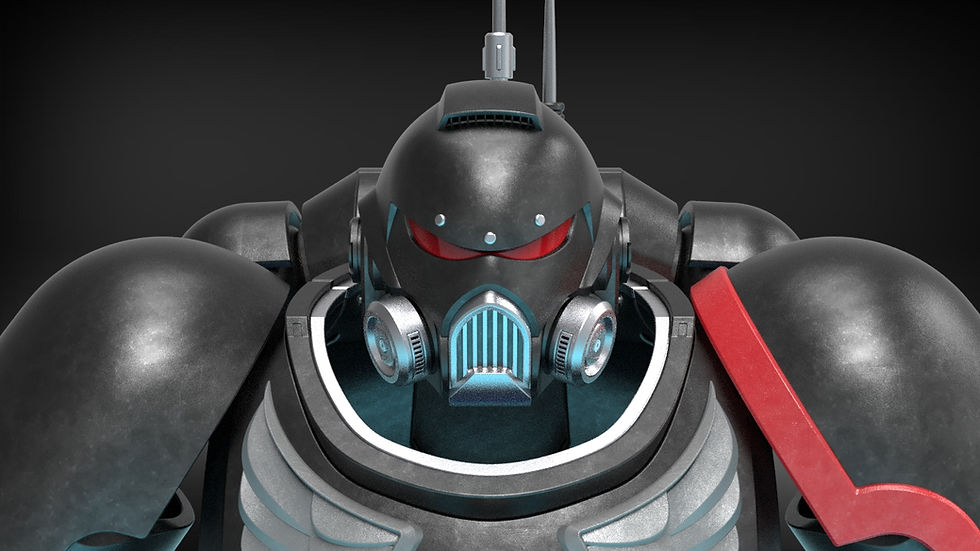

Constellation Suit Build Guide
- josephaguilarsanch

- Dec 16, 2023
- 7 min read
Updated: Jan 31, 2024

The Constellation Suit presented a lot of really fun design challenges
For a full write up of all the features you can find them listed on the main product page.
This Build Guide will list the following:
Require materials to complete the project
Assembly videos to walk you through the assembly process
Recommendations for Print Settings/Orientations for certain pieces
Any additional questions you have concerning the building of this suit can be sent directly to me via the contact page on my website
Build Requirements
Visor Requirements
Non-Required Hardware
Up to a 55mm circular speaker (Hobby speakers that can be powered/connected to the Bluetooth Reciever via a 3.5 mm jack)
Bluetooth Reciever w/ headphone jack (Allows helmet to connect to your phone/computer)
LED Diodes (for the overhead flashlight, will require batteries)
Upholstery foam (for the padding)
Faux Black Leather (for the padding)
Assembly Instructions:


Constellation Helmet
The Build Guide for the Constellation Helmet can be found in its own dedicated build guide
Constellation Boost Pack
Below are written steps to go along with the video above to assist with the assembly of the Constellation Boost Pack
Place the Lower Thrusters within the Body Bottom, a small amount of hot glue will help keep it in place
The Boost Pack Vented Floor can be placed on the small internal lips of the Body Bottom, a small amount of hot glue can help keep this in place as well
Place the 4 Connection Pegs in the Body Bottom
Place the Removable Cover Pegs in the Body Top and Place the Body Top onto the 4 Connection Pegs.
You can now place the Body Port Large an Body Port Small into the Body Top
Additionally, you can place the Removable Cover Button Large and Removable Cover Button Small into the Removable Cover and place it onto the Body Top. There are slots in the Removable Cover as well as the Body Top in which to place the 20x3mm disk Magnets. The Removable Cover is held in place by hooking it into the the Removable Cover Pegs and then having the magnets hold it in place. Hot Glue should be used to keep the magnets in place.
The Thruster Assembly can now be inserted into the Body Top
The Upper Thrusters can be inserted into he Thruster Assembly, completing the Boost Pack!
In order to attach it to the chest rig, place it over the front face of the Boost Pack Mount. Secure it by inserting the 3 Boost Pack Adapter Screws. There are also Boost Pack Adapter Pegs if you want to use smooth pegs and adhesive rather than the printable screws. This makes for a 3d printable screw that can be turned with no specific tool, and will not deform under the pressure of a traditional screw cavity/alan key hole.
Constellation Chest Rig
Below are written steps to go along with the video above to assist with the assembly of the Constellation Boost Pack
Insert the Hinge Arm into the Ab Plate and then place this assembly inbetween the two Hinge Ports on the bottom of the Chest Plate
Insert the two Hinge Pins through the opening in the Hinge Arm and slide them such that they insert into the Chest Plate. This allows the Ab Plate to rotate freelyinside the Chest Plate.
Secure the Hinge Pins by inserting the Hinge Locking Pin, this keeps the Hinge Pins pressed into the sides of the Hinge and prevents them from sliding out. This can hot glued in place if desired.
Next, we can assemble the cannister sub-assembly by placing two cannister Caps on either end of the Cannister Body.
Insert the Cannister into the Chest Plate via the Cannister Connection Peg
*NOT SHOWN IN VIDEO*: the Cross Bar can be inserted into the Chest Plate through the opening where the Large Front Port goes.
All Cosmetic Pieces can now be inserted in their respective places. This includes the Large Front Port, all eight of the Accent Button Small pieces, the Accent Button Large, and the Ab Plate Hatch.
Starting with the Boost Pack Mounting Body, we insert the Boost Pack Mounting Face.
The three Boost Pack Mounting Ports can be inserted through the back of this assembly
We can now connect the Neck Hose Cover and the Neck Hose and Ring Adapter.
This Neck Hose assembly and the Boost Pack Mount Anchor Point can be inserted into the Boost Pack Mounting Plate Assembly
This entire assembly can now be secured together by either the four Boost Pack Body Screws or Boost Pack Body Pegs. All Screws in cluded in this set were designed to be turned with any two pins (such has the tip of a needle nose plier). This makes for a 3d printable screw that can be turned with no specific tool, and will not deform under the pressure of a traditional screw cavity/alan key hole.
Connection Modules:
This section will detail how to assemble the Connection Modules that connect the Chest Plate and the Boost Pack Mounting Plate. In-game there are 4 connection modules and one Chest Plate Anchor per side. I personally only used 3 connection modules as it would be too large on my small frame other wise. You can adjust the number of connection modules as needed to fit your chest.
Insert either the Inner or Outer Cap onto the Connection Module Body. One side needs to be left open for the next step
Insert the Connection Module Bar into both ends of the Connection Module Body.
Insert the remaining Inner or Outer Cap into the Connection Module Body to enclose the Connection Module Bar within the Connection Module Body. This will complete a singular Connection Module
Repeat this process with the Chest Plate Anchor and the Chest Plate Anchor Cap.
Two Modules Can now be joined by a Connection Module Link and two sets of M3 Nuts and Bolts.
The Chest Plate Anchor Can be connected to the chest plate by a length of 1.5" nylon strap. You can then cover this connection with the Harness Cover.
The Harness Cover should be printed in TPU in order provide a flexible cover that can be inserted into both the Chest Plate Anchors and the Chest Plate
The Connection Module can be connected to the Boost Pack Mount Anchor Point by an M3 Nut and Bolt.
Lastly, if desired, the Neck Hose and Ring Adapter can be connected to the Neck Ring by their compatible 10mm holes. A length of hose or something similar can be used to connect the pieces.
Another feature of the Connection Modules and the Chest Plate Anchors are their bottom lips. These bottom lips are used as an attachment point for the leather padding that can be created using the included, printable padding tools.
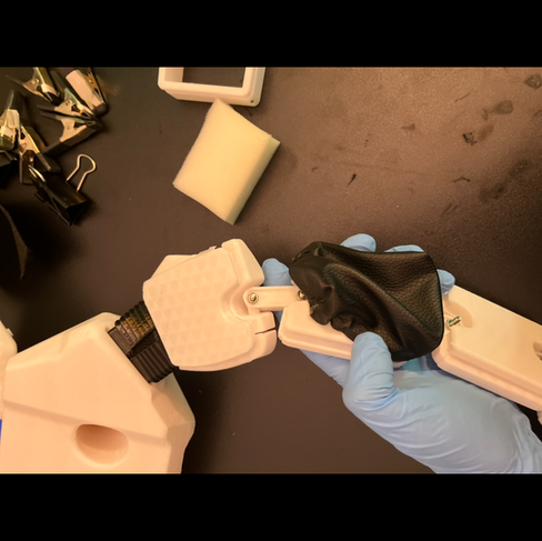
Follow the pictures below to see how I created the leather shoulder pads without any prior upholstery experience.
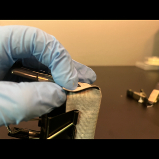
First, use the Leather Template to cut out the shape you'll need for the leather pad.

Stretch this leather pad around the Padding Rig and secure in place using clips/clamps.


You are the going to want to use super glue to close the corners


Once the corners are closed you can place your rubber bands over the entire assembly such that they naturally lie in the grooves of the Padding Rig. For the desired elasticity, I took two rubber bands and folded them such that I had four loops.


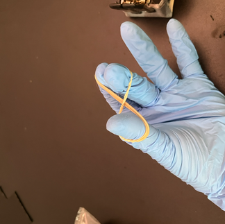


Next, I super glued the folds over the tops of the rubber bands and held that in place using the same clips/clamps such that it had time to cure. A minute should be more than enough time for these connections to cure


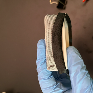


Once everything is cured, I slid the entire pouch off the padding rig and inverted it.

I used the padding rig to cut out a same sized rectangle of foam and inserted it into the leather pouch.


I took my new leather pad and stretched the rubber band lip over the lips in the connection modules. They now hold themselves in place and provide nice padding for each of the connection modules.


General Printing Tips
General printing tips for the helmet can be found in its dedicated build guide
Many of the pieces in the set have large obvious flat faces to align with the build plate, but one easy hack to help print those pieces which have no obvious flat face is to use Cylindric Custom Support downloadable plug-in for the Ultimaker Cura Slicer. It allows you to place custom supports on parts to ensure that you can get much safer and reliable prints on parts with odd geometries. It also helps print tall, thin structures by providing much needed base area and stability.
As mentioned above, many of the pieces have large flat faces that can be used to align with the build plate, such as the Body Top and Body Bottom pieces of the Boost Pack.
The connection module and the Chest Plate Anchor have multiple flat faces that can be used. The vertical orientation can make removing the internal supports easier.


The Removable cover was designed to be printed on its flat sides. The geometry was modeled to minimize the amount of required supports when printed in this orientation.

The Chest Plate has flat top face that I recommend aligning with the build plate.


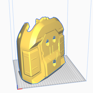
The Abdominal plate has no such flat face so I recommend turning it upside down and printing on its top face with the aid of custom cylindrical supports

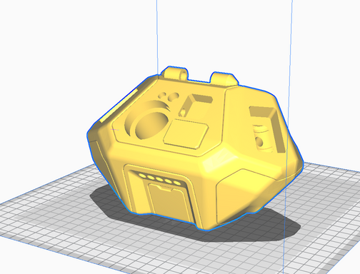
The Thruster Assembly has two options: Its top-most face will require the least amount of supports, but printing on its rear face will ensure that the faces that are most hidden get all the supports.


The Boost Pack Mounting Plate Anchor Point has a nice flat face, but as it is a tall thin wall, I recommend adding some custom supports to the base

The Upper Thrusters also have a flat inside face that can be used to print it as a tower

Load Bearing, Structural Pieces
Any peg or screw type model should be printed on its side such that the layer lines run along the long axis, this makes these pieces much stronger and way less likely to break apart inside of the print. For the screw pieces you may have to give them a quick, rough pass with some sand paper to ensure that therer are no artifacts/ roughness left over from the supports such that they can continually pass smoothly through their cavities, but increased tolerances have been included to help accomodate this.

This also goes for all the connection module links as they will be supporting alot of loading forces with the M3 bolts